Can I have a PET?
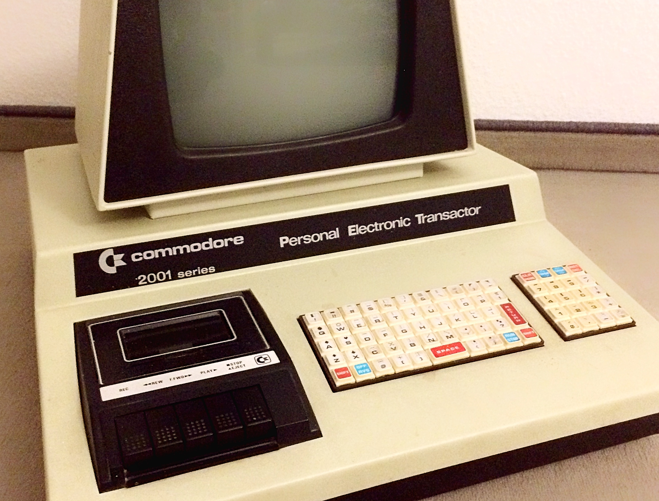
Commodore PET 2001 series - breeding and care
Okay, we all know, what we're talking about, don't we?
A Personal Electronic Transactor, short a PET, introduced by Commodore in the late 1970s.
Up to now, I recently have been working on Commodore VC20 / VIC20 Home Computer. Last weekend I got a call from a good friend telling me that I could buy a PET-Computer in a reasonable condition. The only drawback is that it's not working. OK, we have something on the screen, which means, that it isn't completely gone.
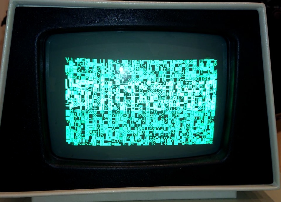
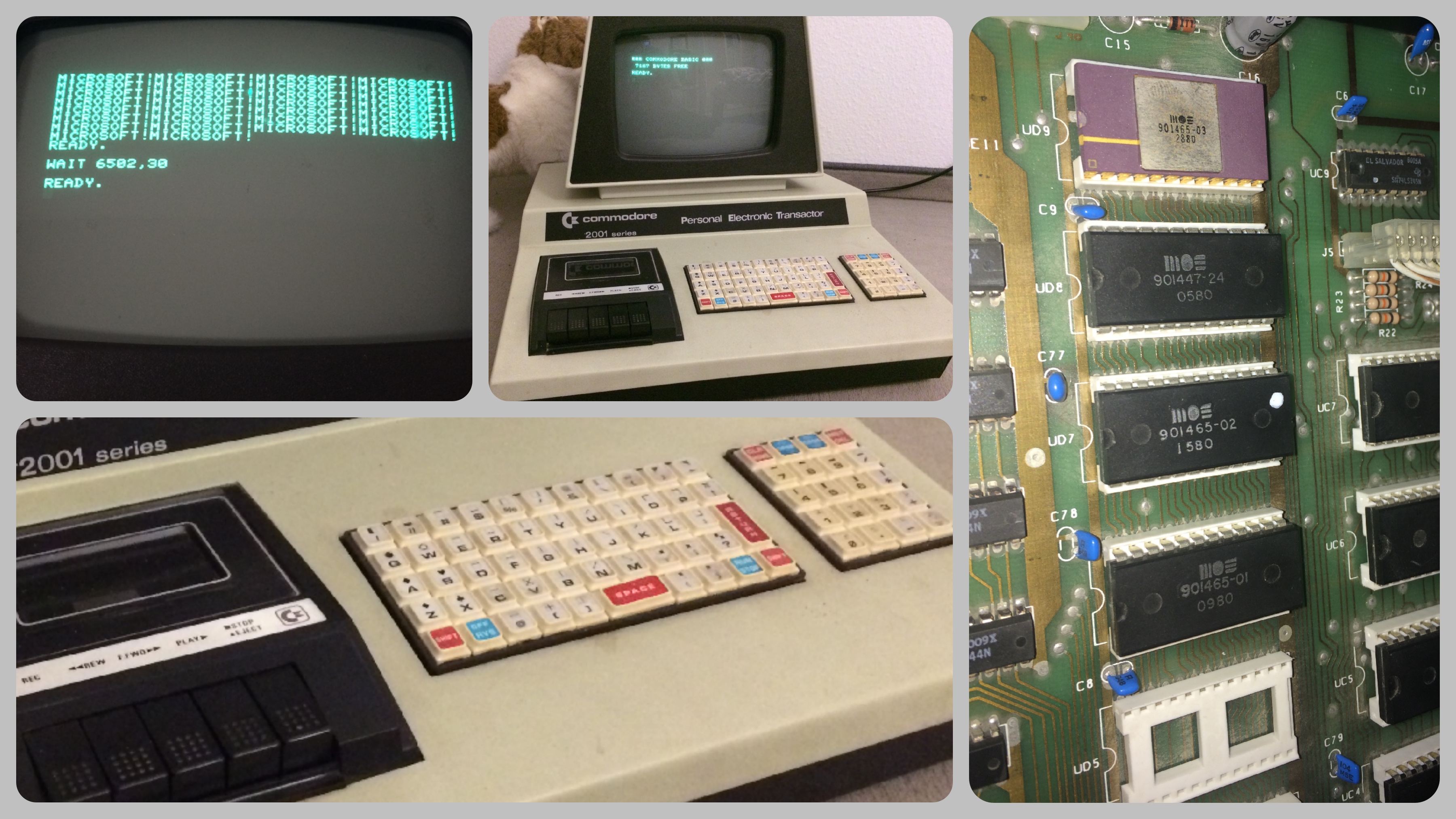
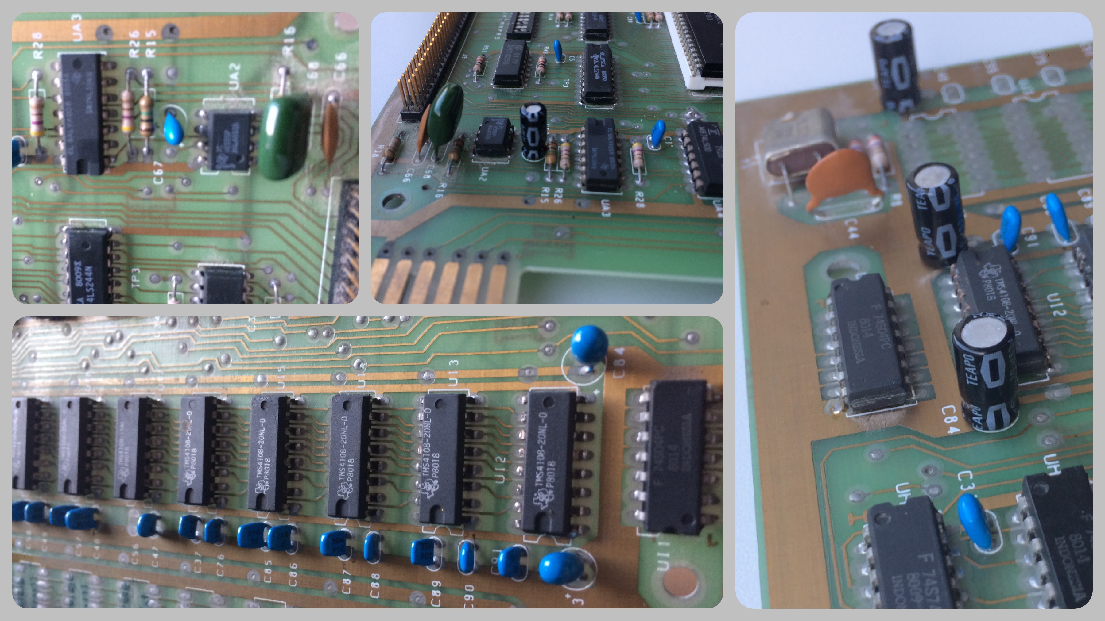
Garbage Screen - something extremely typical for the PET, some people say, it's not a bug, it's a feature! If the CPU or the memory or the ROMs aren't working, you get this message. NO, there is now hidden message behind the letters on the screen! The fact that we can see this garbage is that the TTL-logic behind the discrete character generator is working, but the startup sequence isn't firing up. And as we have learned, this can have almost half a trillion of causes: Bad CPU, bad connections, bad power, bad CIA / VIA, bad ROMs -very common-, bad RAMs - even more common-, both latter especially in the very first series with the MOS 6550 RAM chips and the MOS 6540 ROMs. But I didn't want to buy the pig in the poke. Luckily, the guy selling the machine was really very nice, so I could take a look inside the cabinet. To my surprise, it had a different board than I expected. This particular one was populated with TMS4108 DRAM chips and the much more common 2316 / 2332 ROMs. So it must be a very first Dyn-PET 2001 series. These boards later were used in the CBM 30xx Commodore machines, when Commodore had to change the name PET to CBM for the European market (Philips had already taken the rights of this name for their own Programm-Entwicklungs-Terminal).
To make a long story short, I bought this machine and couldn't wait to see it working. But it was a long and winding road from the 'yes, it's mine' to the 'mission complete' of a great looking and superbly working piece of computer history. But one by one ...
As always you have to know your enemy. So studying the schematics is essential to succeed. An excellent point to start is zimmers.net. This sounds a bit unbelievable, but IMHO you can find almost everything regarding commodore on his FTP Server. And really, here you can see that commodore had produced this very exotic computer. The assy number 320351 is correct, and it is a version with 8K and an internal cassette drive. So it must be a 320351-06 or -12, great! So I studied the schematics and -as always- checked the voltages of the power supply. Touching the connector with the probes I heard a buzzing sound and the screen became blank. Oh no! I was sure I didn't made a mistake. OK, take a deep breath, turn it off, turn it on again - garbage screen - OK - blank screen - what?
It took me a while to understand, that this is not another issue but we are stepping ahead. The startup sequence became alive - so the CPU and at least the uppermost ROM - to clean the content of the screen RAM. But there was this buzzing sound, I have to checked the connector:
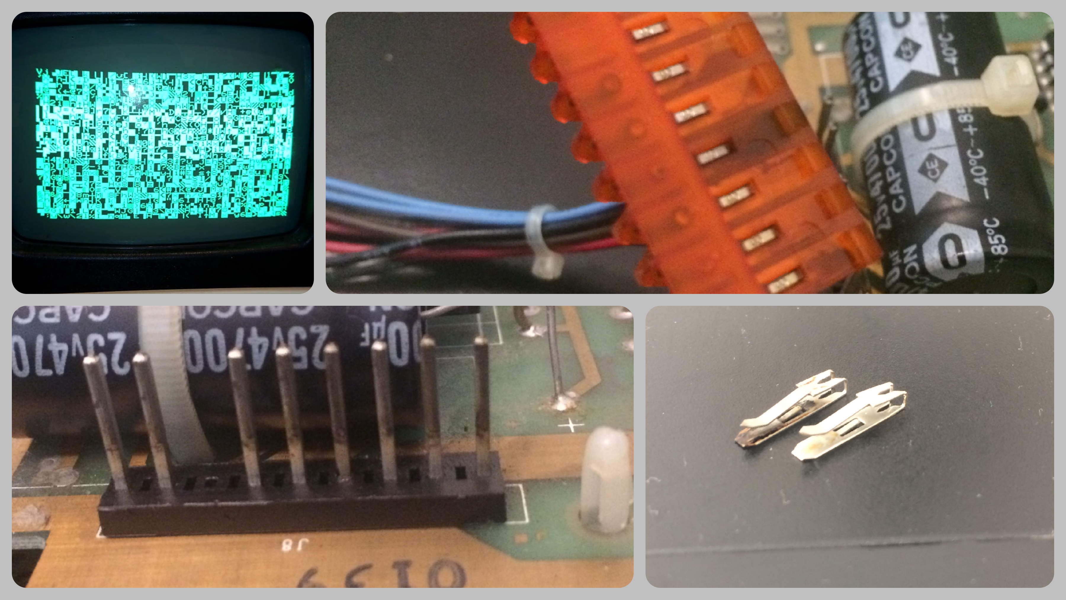
Bingo! Yes, I have bad eyes but even I can see the brownish part in the red plug. and the pin header speaks the same language. So after many years the connections became bad, this heated up the connector, the connections became worse and so on .... Luckily there is a spare part inside this plug. The key- pin on the header isn't populated, but the unused part in the plug is there. You can see both of them in the picture above, one shiny, the other one rotten. After this first step I checked the voltages again, this time everything is fine. But the screen stayed blank. I took my EEPROM programmer with the corresponding 2364 adapter and read all the ROMs. No issues, all were tested fine. Still the startup sequence - garbage - OK - blank - OK - but there was no message saying Commodore Basic.
Perhaps it's something wrong with the RAM? I checked the voltages -sic- voltages!!! These DRAM are powered with +5Volts, -5Volts, and -last but not least- +12Volts. And the latter was missing! I only measured 0.2Volts, almost nothing! OK, checking the voltage in front of the 7812 reads +18Volts - fine. On its output I had +0.27Volts. On the DRAMs I had +0.2Volts. OK, I had a drop of 0.07Volts on the copper wire of the circuit board. Something is blocking the +12Volts power rail, but what? The DRAMs? Nope, they didn't warm up at all! So I traced the copper wire from the 7812 almost to the front of the board where you can find a bank of capacitors, to the rail along the DRAMs. I measured again along the trace and - wait a minute - the drop stopped at the capacitors!!?? OK OK, I'm an older guy, once again: +0.27Volts output on 7812, check, +0.2Volts at the capacitors, check, and even 0.2Volts at the DRAMs. This means the short isn't caused by the DRAMs but by the capacitors? I had a foreboding: a long time ago I had a lot of trouble with a tantalum capacitor blocking the power of a small battery powered circuit. This capacitor was short! Could it be possible, that one or both cause the shorting of power? Without blowing or heating up? While heating up my rework station I calculated: the 7812 is limiting the current to 1Amps, and we are taking about 0.2Volts, which means 0.2Watts for the capacitor. That's almost nothing, at least not enough to blow up the tantalum. I removed both of the capacitors responsible for the +12Volts and replaced them with two regular capacitors.
Keeping the fingers crossed I switched on the power: - garbage screen - OK - blank screen - OK -
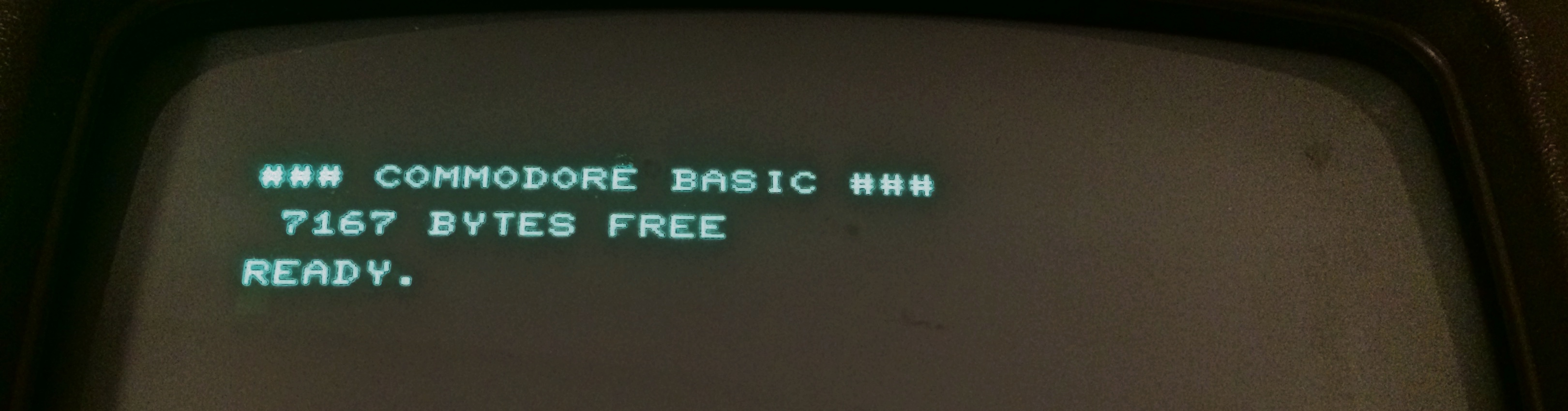
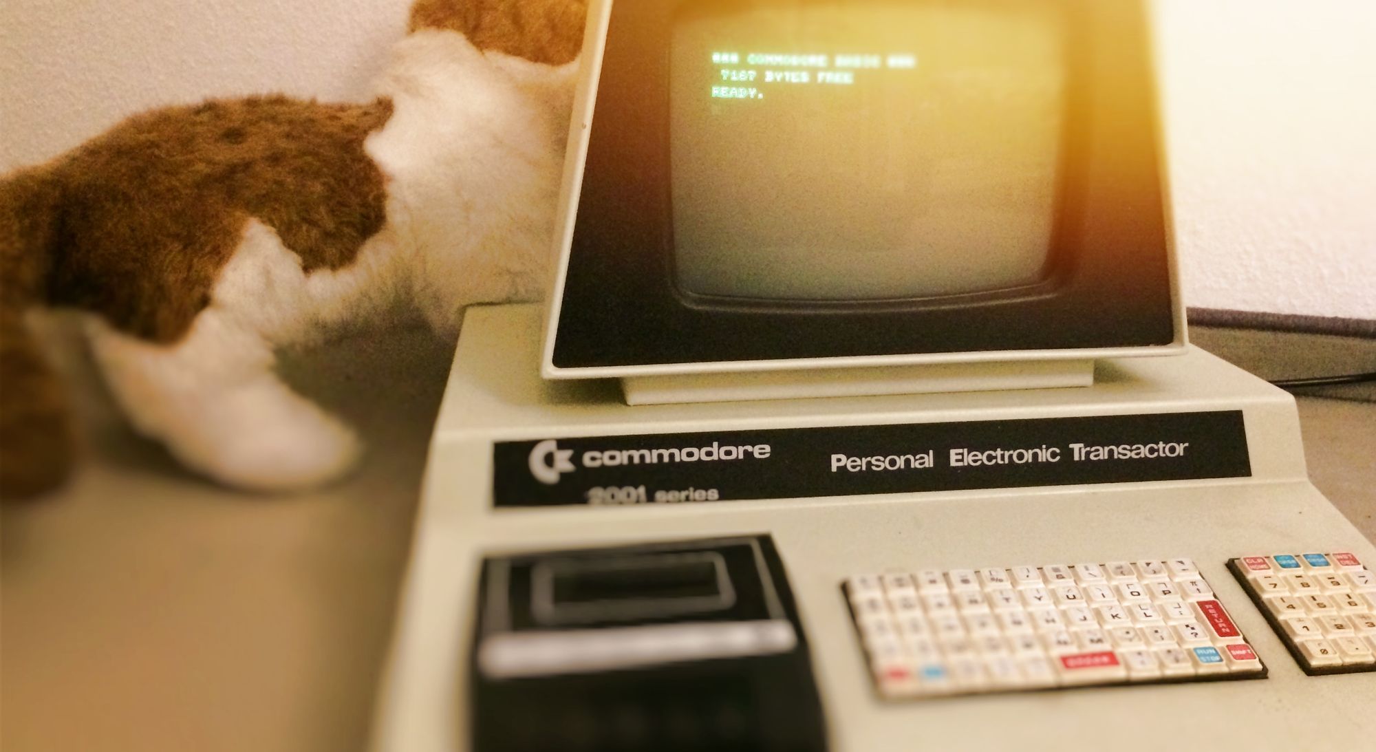
My heart skipped a beat when I saw this little innocent message on the screen. But it is true - system up'n'running. Checking the keyboard - fine! But I didn't wanted to have the other old tantalum capacitors on the board. If one fails, who's gonna assure the other working? I didn't want to wait until the next of these nasty little beasts ruins my day. So it's time to heat up the iron ...
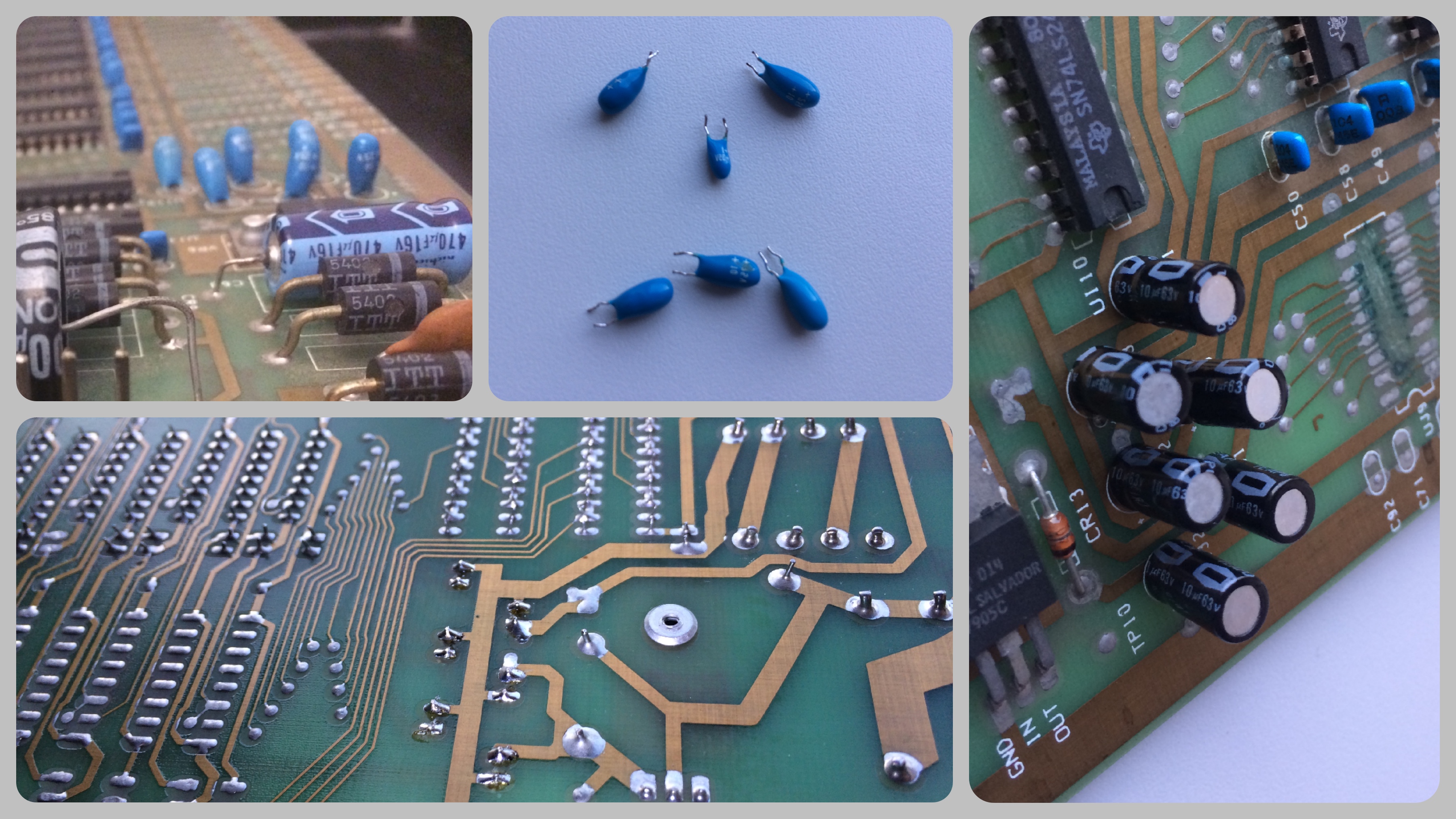
I banned ALL of them, at the mentioned capacitor bank, at the end of the power rail and even the one at the NE555 controlling the reset circuit.
While removing the flux I noticed the stained edge connectors! After the cleaning they look like new. And there as another thing I became aware of: scratched traces located at the unpopulated DRAM section UJ7 - UJ9. 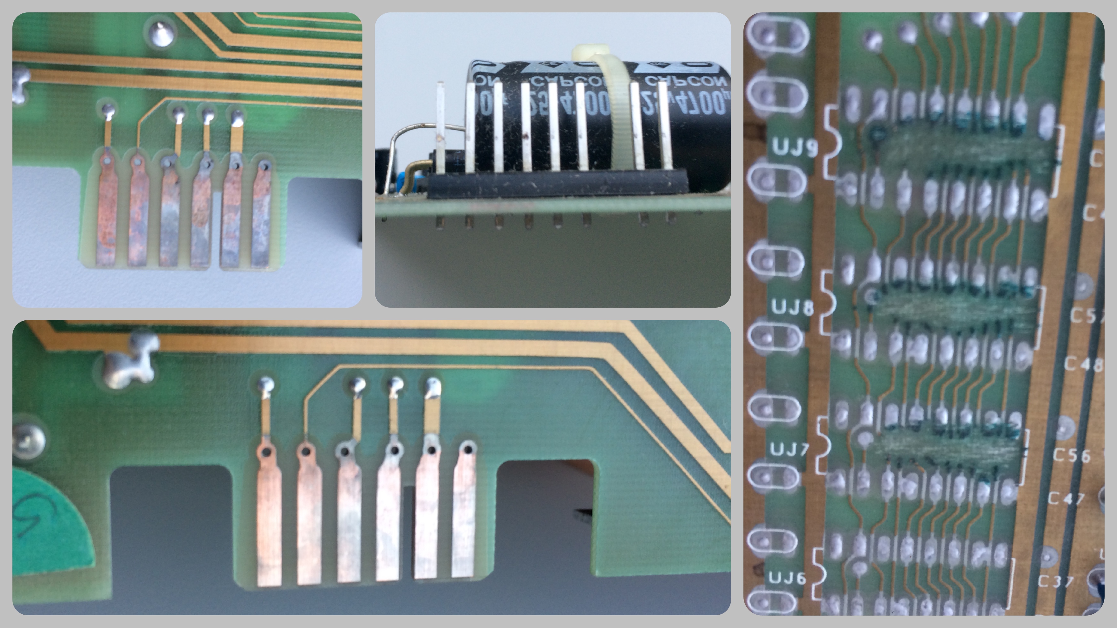
Well, I read the article in The PET Paper, Volume III, Issue 8/9/10, Feb/Mar 1981, where the author complained about Commodore's way to make even more profit:
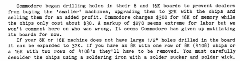
Drilled holes in the PCB, big holes, half an inch! What I got here is a different way to prevent dealers or people with electronic skills to upgrade their computer.
But anyway, that's history! And I'm happy with my new old Commodore PET. It's a little beauty, and sure: Bill Gates came by giving Jack Tramiel this nice little easter egg with the WAIT6502,1 or even more, if you like