I need a workbench
A What? Workbench? We are talking about classic computer, sure?
OK, OK, not a workbench in the true sense, but some sort of a sturdy place I can start to check all the magic chips made by M.O.S. like 6502, 6522, 6560, 6561 ...
As an electronics technician I don't want to stress out these little sockets underneath the microchips ( and the chips themselves ), and sometimes it drives me nuts to fiddle these centipedes out of their habitats.
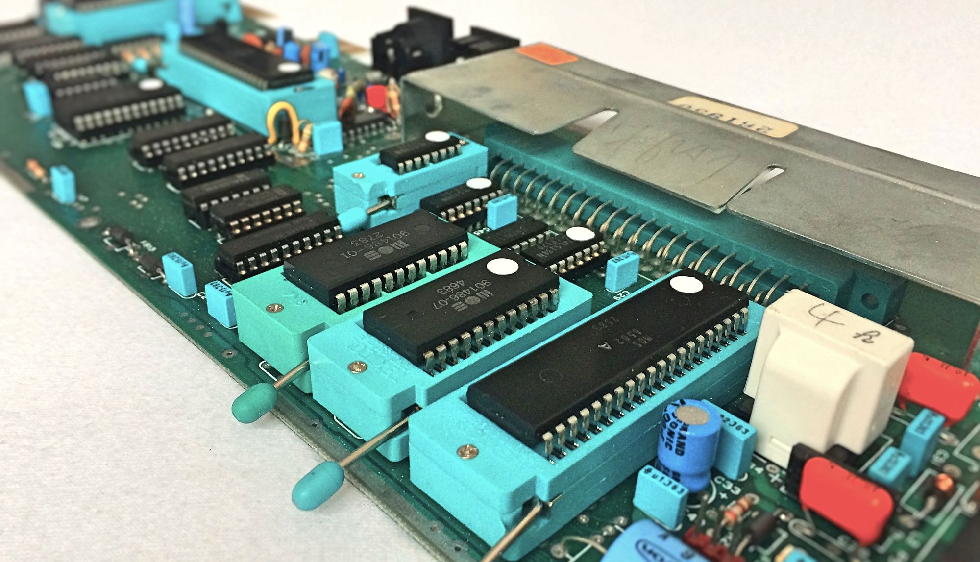
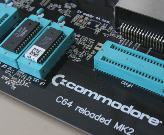
Well, what inspired me was the sight of this technical marvel of a C64 Reloaded MK2, it's like a piece of art. And yes, I liked the idea of these wonderful easy to use ZIF sockets. I would be able to swap out all my 40-leged bugs within seconds.
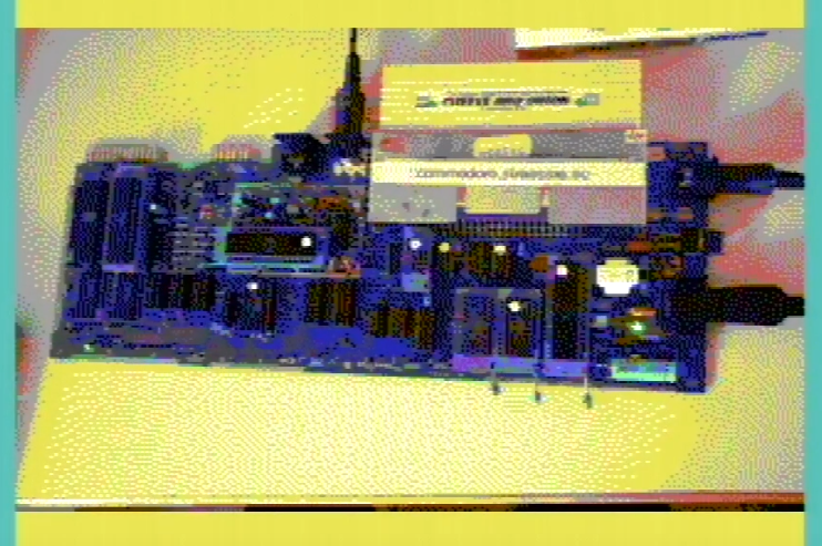
Let's do this with a VC20 / VIC20, and with the genuine board:
Fortunately I had an old broken VC20-CR board handy. This is an ideal candidate for the upcoming process. But this poor little guy had some issues:
OK, this gives me a wonderful win-win game. Repairing this board and making it a platform to repair other VC20 / VIC20 and the corresponding microchips.
First of all, I recently desoldered all of main microchips from the PCB, because literally none were mounted in sockets. So, after that I decided to use ZIF sockets for all the bigger ICs (CPU, VIC, VIAs, ROMs). Sometimes it is necessary to mount the ZIFs in the opposite orientation to make some room for the lever.
Hereafter it became obvious, that NONE of these microchips were broken. I tested every single one of them in a different VIC, so far everything's fine. But the board itself didn't work.
I was in parallel doing some programming on my test cartridge for the expansions port, and this showed that the cartridges ROM code was read by the cpu and executed correctly, but there was no control over the memory (RAM).
Digging a little bit deeper into the VIC20's circuit diagram it became evident, that there's a difference between the CD(ata) lines an the corresponding VD(ata) lines. Some of these data bus signals are shared between the CPU and the VIC, especially the signals to the RAM. To make sure, that everyone of the CPU and the VIC are in sync, there are several clock signals, deriving from another. So checking these clock signals with an oscilloscope gave me many working signals, but one was missing:
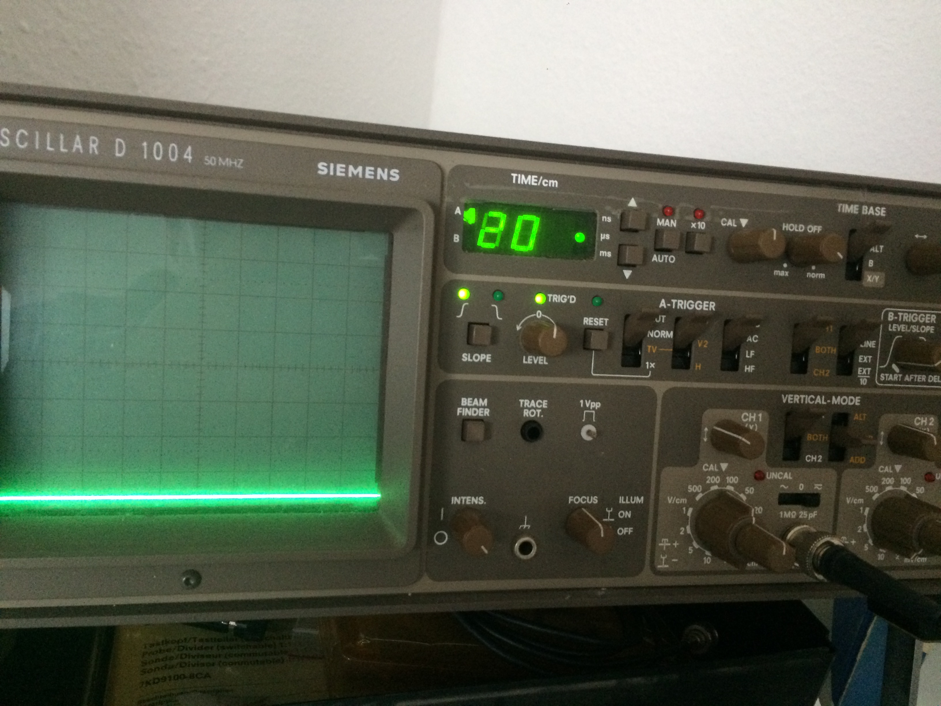
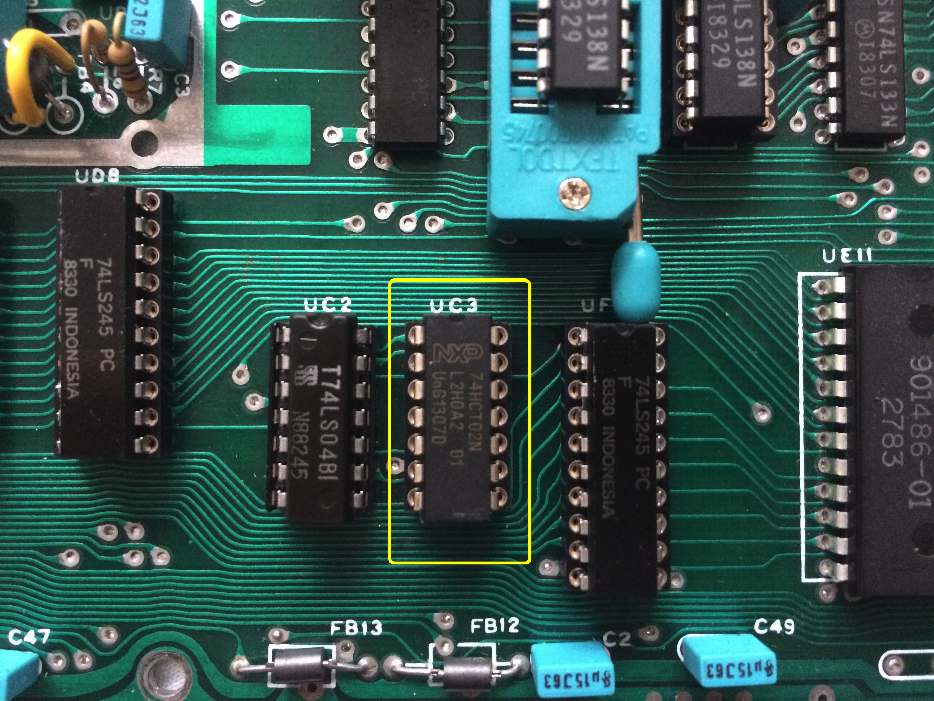
On FB12, which is an ferrite bead, was NO signal at all. Bingo! The clock phi1 wasn't here. This board couldn't work.
So I replaced IC UC3, and - keeping the fingers crossed - switched on the power.
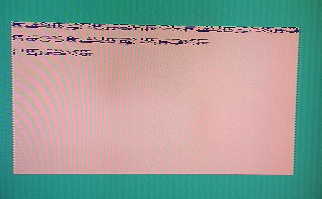
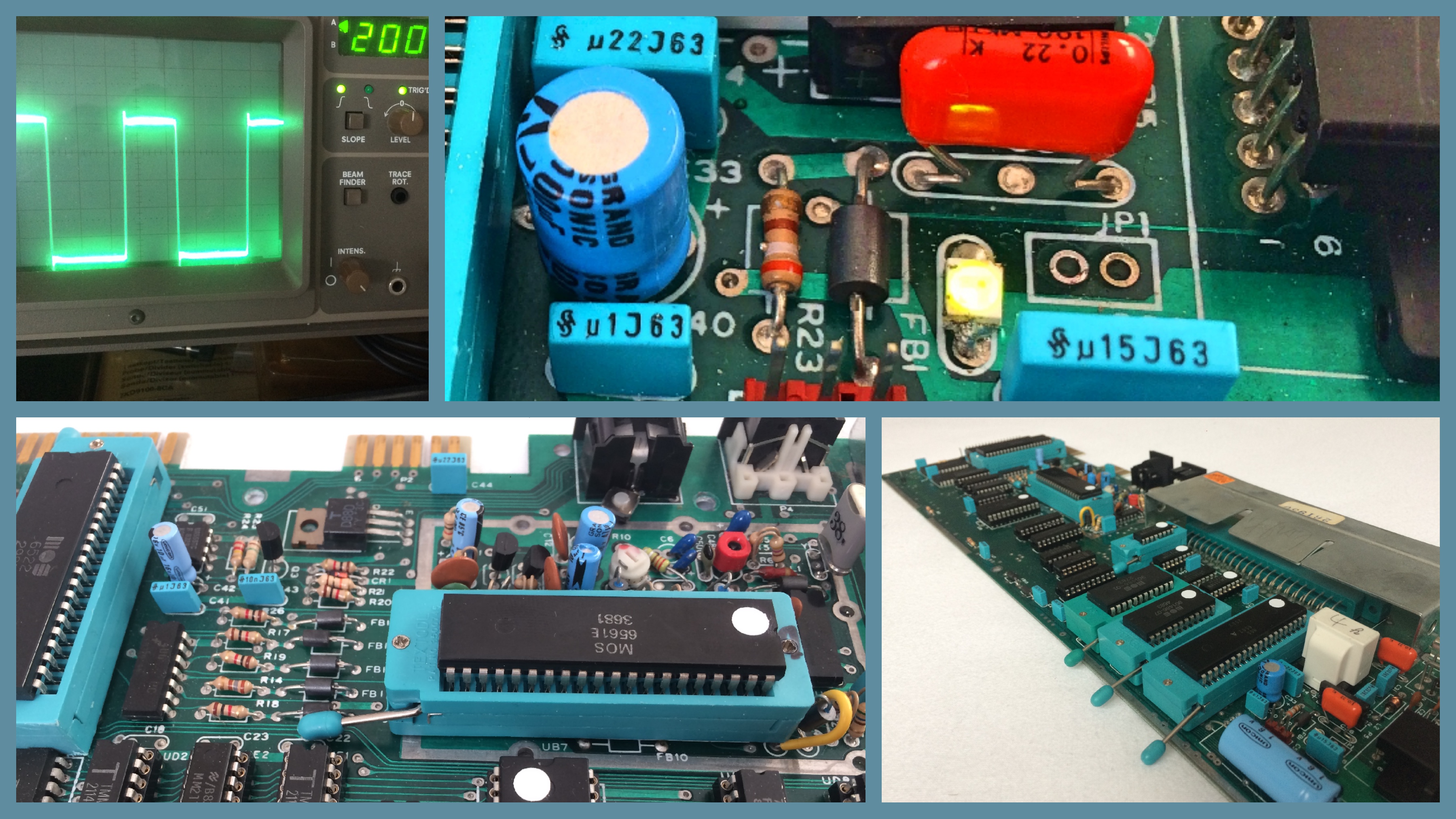
TADA!
Everything's fine now! Back alive. What did we learn in that short story? Sometimes there are small parts that can ruin the day.
And finally I have my workbench with all these fancy turquoise ZIF sockets, turquoise capacitors and green power LEDs mounted on the board.
You like to see this board in action? Playing the NEW cartirdge game Cheese And Onion? Take a look here at HomeCon 53 NuVie video: